Drawing Trees in Plan Illustrator
Tree Diagram
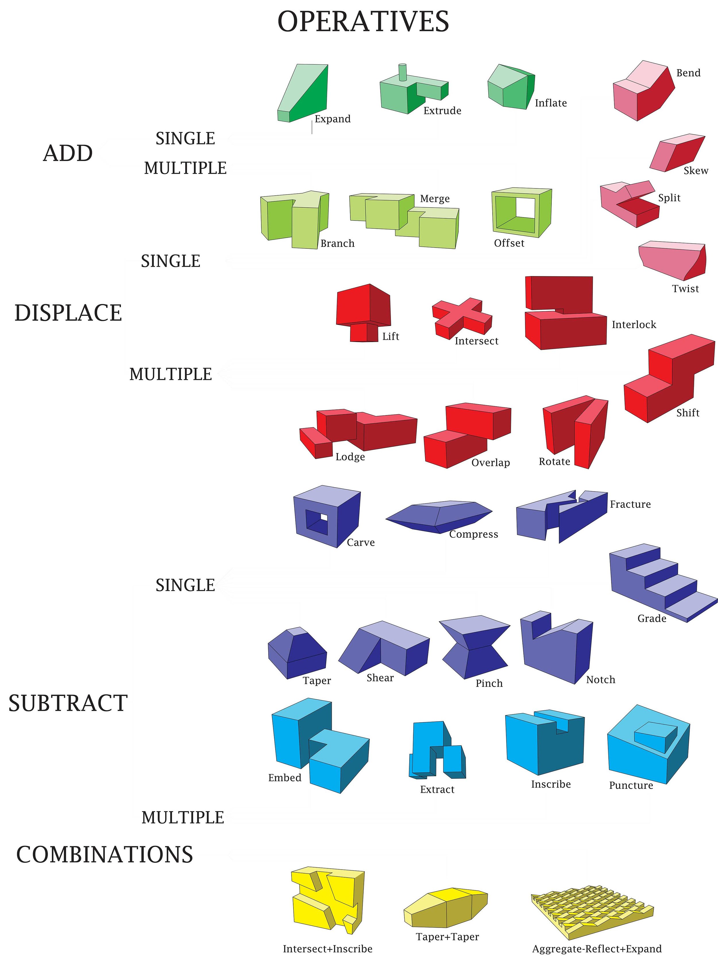
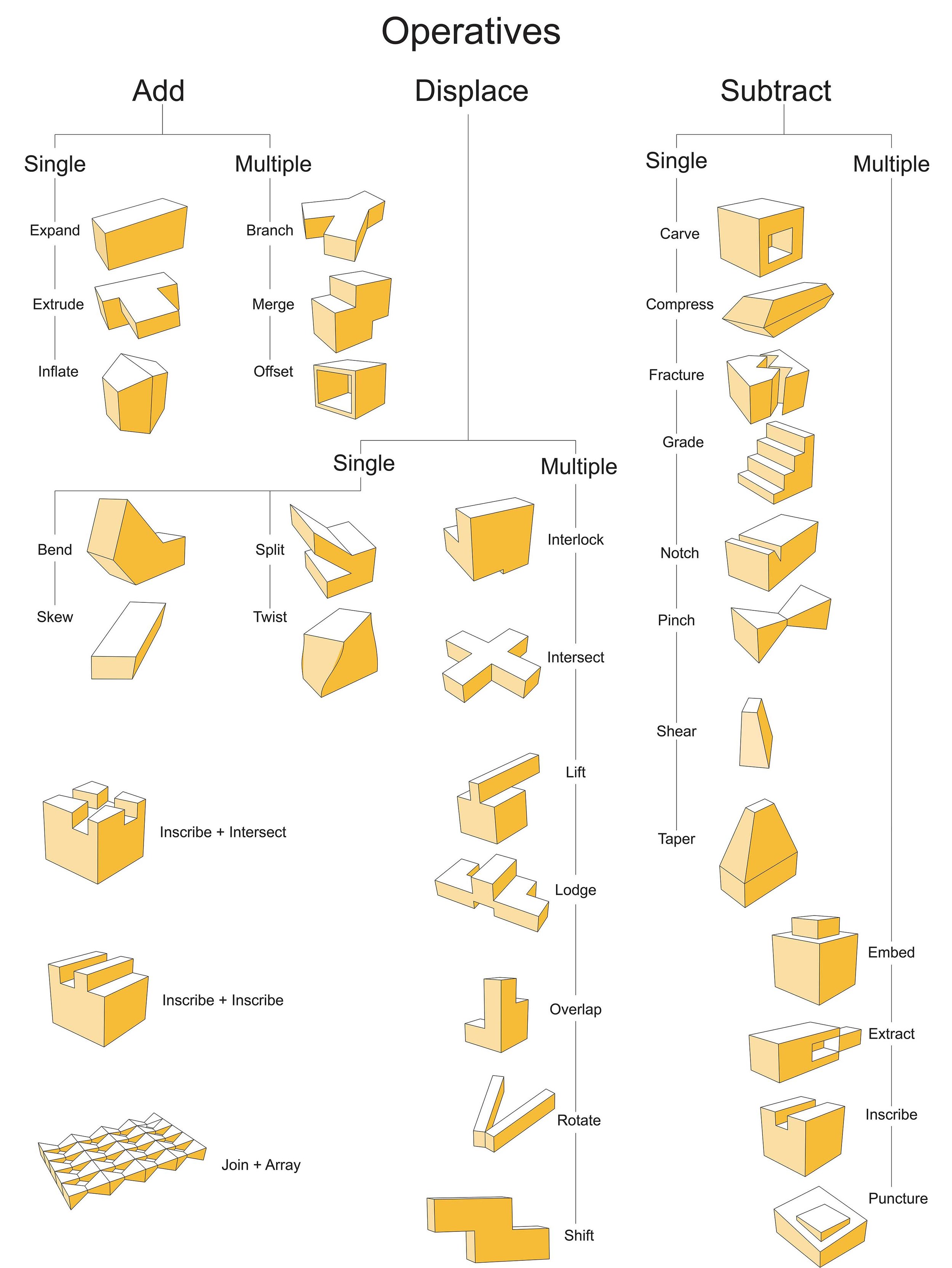
In this exercise you will be making diagrams from the 3D models that you built in Rhino, and you will be arranging them on a sheet in Illustrator. The diagrams will be arranged as a tree diagram. Refer to pp. 16 & 17 in the book titled Operative Design: A Catalog of Spatial Verbs. Your tree diagram will include all of the text shown on those pages plus diagrams of each of your models.
Part 1 - Exporting the models from Rhino to Illustrator
TD1.1. Open the Rhino file called Operations-Add. Erase the Base Volumes.
TD1.2.In the Perspective viewport compose the first model, Expand operation. Choose an angle that illustrates the operation.The image below is shown in the Ghosted visual style.

TD1.3.At the command line enter MAKE2D, select the object and press Enter. In the 2D Drawing Options dialog box select the Perspective view and uncheck the Hidden Lines box.

TD1.4.Zoom to the extents of your Top viewport by typing Zoom and selecting the Extents option. You should see that a 2D drawing has been created close to the 0,0 coordinate. If it overlaps the 3D models in your file, move the 3D models out of the way.

TD1.5.At the command line type EXPORT. Select all of the lines of your 2D drawing, and press Enter. Name the file with your initials followed by the operation type. In this case it is the Expand operation. When the AI Export Options window appears, accept the defaults and click on OK.

TD1.6.Erase the lines of the 2D drawing in Rhino.
TD1.7.Repeat this process for all the operatives from Parts 1, 2, 3 & 4.
TD1.8.In the Google Drive make a folder called 2D Rhino Diagrams in the main folder for the class. Upload all of the files to your Google Drive folder. I will move them into another folder once they have been reviewed. You may want to keep a folder with these on a usb also. You will need the files for the next part.
Part 2 - Setting up the Illustrator sheet.
TD2.1.Open Illustrator.

TD2.2.Create a new File. Go to the File menu and select New. Use the settings and file name structure shown below.

TD2.3.Go to the File menu and open the first 2D drawing (YourInitials_Expand).
TD2.4.Type Ctrl + C at the same time to copy the image to the clip board.

TD2.5.Toggle to the Operative Design file by clicking on it. Click on the X next to the Expand file to close it.

TD2.6.Click on the New Layer icon. Layer 2 will appear.

TD2.7.Double click on the layer name to rename it. Rename each layer to identify the operative (eg. Expand). The layer with the blue/gray highlight is the current layer.

TD2.8.Type Ctrl + V at the same time to paste the drawing into your layout. The drawing will be very small on your sheet. You can scale it later, but it would be best to move it from the center because each small drawing will paste into the same spot. To zoom in closer type Ctrl + + at the same time. To zoom out type Ctrl + - at the same time. To move the small drawing make a window around it, and left click on one of the lines. Hold the left button down and drag the drawing. To deselect double click at a spot outside the small drawing. You can also use the arrow keys.

TD2.9.Before proceeding it is recommended that you have an idea how you will arrange your drawing. You can make adjustments later as well.
TD2.10.Repeat the steps above for the next operative drawing. Make sure that you create a new layer for each drawing. To see that objects are on the correct layer, click on and off the eye icon next to the layer name. Bring in all 29 diagrams.
TD2.11.Turn on the rulers. You will find them under the View menu.

TD2.12.Next create a layer for text.
TD2.13.Create text using the Type tool. Make a box by clicking two points in the layout. Choose a font. Center justify the text. Set the font to 100 pt. Type Operatives in the box.


TD2.14.Repeat for the remaining text. 80 pt font is recommended for Add, Displace and Subtract. 60 pt font is recommended for Single and Multiple, and 40 pt is recommended for the remaining text. You can change text by double-clicking on it. You can change the font font by highlighting the text. You can use Ctrl + C and Ctrl + V to copy and paste text. Arrange them in their approximate places.
TD2.15.Next you can scale the drawings. Before proceeding make sure that you have arranged your drawings roughly in their final positions. Do your best to fill the sheet without making the images too close. The 2 Combination drawings and the Aggregate drawings should be on the sheet, but do not need to be part of the tree structure. To scale a drawing make a window around it, hold down the Shift key while stretching the drawing from its corner.

TD2.16. Next you will be making the lines of the tree diagram. One way to make a line is to select the line tool along the menu on the left. Left-click a point and hold down the button. Press the Shift key to constrain movement horizontally or vertically. Release the button to select the second point. The other way is to left-click and release. You will be prompted to give an angle and length for your line.
TD@.17. If you do not see the line it may not have had its color define. If it is not black, double-click on it to set the color. Select a point within the black range, and click OK.

TD2.16.Use the Line tool to draw the lines in your diagram. Making lines in Illustrator can be cumbersome. If you make one horizontal and one vertical line, you can make copies of them and then stretch them as necessary.

TD2.17.The image below show the beginnings of the linework. Linework is not necessary for the 2 Combinations drawings and the Aggregate drawing.

TD2.18.Next you will be filling areas of your drawings with color. Set the current layer to one of your drawings.

TD2.19.Select the objects that will receive fill.

TD2.20.Choose the Live Paint Bucket tool.

TD2.21.Choose a color. This color will represent the side of the volumes in shadow.

TD2.22.Click inside the area that will be filled.

TD2.23.Click on the fill color box again. This time choose a lighter value within the same hue.

TD2.24.Select an area that will be in partial light.

TD2.25.Apply the same colors to the same sides for all diagrams so it appears that you have one light source. If you need to match a color that you have already used, you can use the Eyedropper tool. After you have selected the new drawing you want to fill and you have clicked on the Live Paint Bucket tool, click on the Eyedropper tool and then click on the color in one of your other diagrams. You should see that the fill color box has updated. Click on the Live Paint Bucket tool again and select the area within the drawing that you want to fill. Having trouble with this? See below.

TD2.26.If areas that you do not want to fill are filling in like below,...

then right-click and select Isolate Selected Group. Continue working with your Eyedropper Live Paint Bucket tools.

TD2.27.If the lines of your drawing have disappeared like below,...

select the drawing, and change the lines to black.

TD2.28.As you finish up your tree diagram, check and make sure you have done the following: Each operation from the preceding exercises is represented. Areas have been filled with a color to represent the shaded sides. The text from pp. 16 & 17 of the book is included. Linework for the diagrams appears. Linework supporting the structure of your tree diagram is included. The diagram should be orderly. Text should be aligned. The diagrams should be scaled so there is not too much white space, but not so crowded that the diagram is difficult to read.
TD2.29.Make a pdf of your Illustrator file. That way you will be able to open the diagram without Illustrator. Save your Illustrator file. Upload your Illustrator file and your pdf to the main folder. I will move it once I have graded it.


Source: http://www.cccarchitecture.org/tree-diagram
Belum ada Komentar untuk "Drawing Trees in Plan Illustrator"
Posting Komentar